 Band-limited square waves
Introduction
In the field of audio signal processing, square waves seem easy to generate but require some care to get a high-quality result. As shown in the samples below, a naive rendering of a square wave will have noise and harmonic distortion, whereas a correct rendering sounds clean and undistorted.
Square waves are simple audio signals that are useful in practice. For example, early electronic devices could only generate square waves for melodic tones, because they are computationally easy to produce. This was the case for early personal computers, and first-generation game consoles like the Nintendo Entertainment System (NES) and Game Boy. Square waves were later superseded by more powerful technologies such as FM synthesis and sample-based synthesis.
In old electronic products, square waves were synthesized based on control parameter values (e.g. frequency, amplitude, duty cycle, offset) and the signals were sent directly to an analog audio output. But nowadays a lot of audio processing happens in sample-based formats. To play a square wave on a modern computer, the signal must be rendered as a sequence of samples in discrete time and sent to a sound adapter (which is designed only to accept samples, not synthesis parameters). Also, rendering a square wave to samples is convenient for playback (e.g. in any music player software) and for lossy compression (e.g. MP3, Vorbis).
The process of rendering a square wave to a sequence of samples has some pitfalls. The naive way is to simply flip back and forth between the values −1 and +1 at the appropriate sample positions. But a square wave has an infinite number of (non-zero) harmonics, extending to arbitrarily high frequencies. A sample-based waveform must be band-limited to half the sample rate to prevent aliasing – for example, a wave file sampled at 48 kHz can only contain frequencies from 0 to 24 kHz, no higher than this. The naive rendering method suffers from not suppressing frequencies above the Nyquist limit, and from inexactness when the square wave transitions from −1 to +1 (or vice versa) at a point in time that is in between two sample points.
Wave samples
Here is an illustrative 440 Hz square wave, rendered in the simple naive way versus the correct band-limited way, at different sampling rates.
Audio
| Sample rate | Naive rendering | Band-limited rendering |
|---|---|---|
| 8000 Hz | ||
| 11025 Hz | ||
| 16000 Hz | ||
| 22050 Hz | ||
| 24000 Hz | ||
| 32000 Hz | ||
| 44100 Hz | ||
| 48000 Hz |
In the naive square wave renderings, notice the buzzing noise (e.g. 24, 32 kHz), spurious low-frequency tones (e.g. 8, 16, 24 kHz), chopped-up tone sound (e.g. 8, 11, 22 kHz), and inconsistent timbre depending on sample rate (e.g. 22 vs. 24 kHz).
In the band-limited square wave renderings, notice the pure and steady tone, free of any distortions. The sound becomes more shrill as the sample rate increases, but the basic quality stays the same.
As the sample rate increases, the naive renderings have less audible artifacts. This is because in the limit as the sample rate goes to infinity, the waveform of the naive rendering approaches the band-limited rendering. To produce a band-limited square wave, it is certainly possible to render a naive square wave at a very high sample rate, and downsample it properly using a band-limited sinc filter. But in practice (as I argue on this page), it is easier to directly generate a square wave that is band-limited by design.
Pictures
| Signal ╲ Visualization | Waveform | Spectrogram |
|---|---|---|
| Naive rendering |  |
 |
| Band-limited rendering |  |
 |
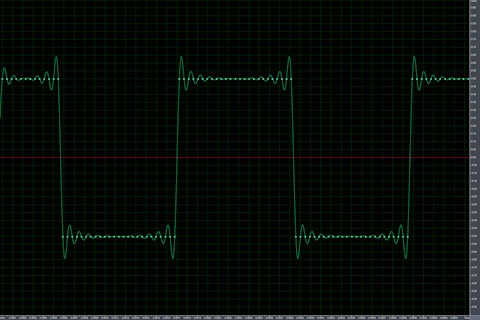
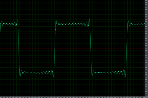
In the waveform pictures, there isn’t a big difference between the naive and band-limited renderings. The naive rendering purely uses the values −0.5 and +0.5 (ignore the interpolated curves), whereas the band-limited rendering uses all sorts of values surrounding −0.5 and +0.5, and has noticeable ringing.
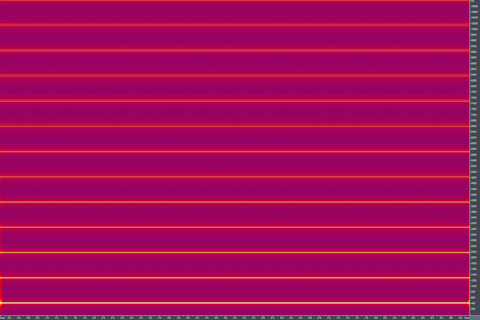
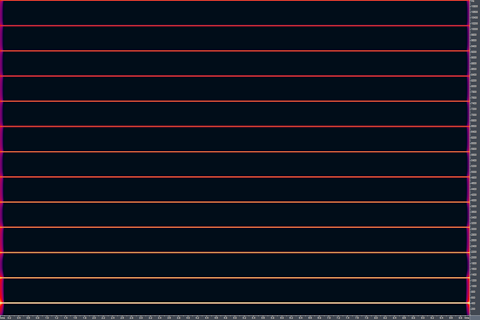
In the spectrogram pictures, the difference between the naive and band-limited renderings is night and day. The naive rendering is full of noise between the real harmonics and extraneous frequencies surrounding the harmonics. The band-limited rendering is clean (ignoring the endpoints due to sudden start/stop), containing only the true harmonics and zero other content.
These screenshots were taken in Syntrillium Cool Edit Pro 2.0 (which evolved into Adobe Audition). Note that CEP2’s built-in square wave generator uses the naive algorithm, with results being essentially the same as my naive implementation. Thus, even commercial software used in audio production can get this wrong.
Generator demo (JavaScript)
| Wave type: | ||
| Frequency: | Hz | |
| Duty cycle: | ||
| Volume: | % | |
| Number of harmonics: | ||
This JavaScript application uses the Web Audio API, and is supported in most browsers except Microsoft Internet Explorer. The source code is available for viewing.
Pseudocode
- Naive synthesis algorithm
-
theta = sampleIndex × frequency / sampleRate.
sampleValue[sampleIndex] = if (theta mod 1 < dutyCycle) then 1 else 0. - Band-limited synthesis algorithm
-
coefficients = (... finite length array ...).
theta = sampleIndex × frequency × 2π / sampleRate.
sampleValue[sampleIndex] =
coefficients[0] × cos(0 × theta) +
coefficients[1] × cos(1 × theta) +
coefficients[2] × cos(2 × theta) + ⋯ .This pseudocode omits how the coefficients are determined. They are discussed in the next section on Fourier analysis.
Fourier series analysis
To synthesize a band-limited square wave, we need to know the amplitudes of each harmonic frequency, and only use harmonics that are below the Nyquist frequency limit (hence setting all higher harmonics to zero amplitude). The Fourier series method allows us to figure out these coefficients/amplitudes. To start, we illustrate a canonical square wave used in audio engineering, which alternates between the values −1 and +1, has a duty cycle of d (between 0.0 and 1.0), and has a period of P = 1/f:
But to make analysis easier, we shift and scale the waveform in time and amplitude into this form, so that it alternates between the values 0 and 1, and has a period of 2π:
Because we created an even function, only the cosine terms (ak) of the Fourier series matter. The sine terms (bk) are all zero. The zeroth harmonic, also known as the DC offset, is clearly \(a_0 = d\). As for the AC coefficients, for each \(k ∈ \mathbb{N}^+\):
\(\begin{align} a_k &= \frac{1}{π} \int_{-d π}^{d π} (1)(\cos(kt)) \: dt \\ &= \frac{2}{π} \int_{0}^{d π} \cos(kt) \: dt \\ &= \frac{2}{π} \left[ \frac{\sin(kt)}{k} + C \right]_{t=0}^{d π} \\ &= \frac{2\sin(kd π)}{k π}. \end{align}\)
Therefore, our list of cosine coefficients \((a_0, a_1, a_2, a_3, \ldots)\) are \((d, \frac{2\sin(dπ)}{π}, \frac{2\sin(2dπ)}{2π}, \frac{2\sin(3dπ)}{3π}, \ldots)\). This is for a wave with duty cycle d that nominally goes between 0 and 1 (subject to overshoot and ringing).
For a wave that goes between −1 and +1, the \(a_0\) coefficient is affine-transformed, and all the remaining coefficients are doubled. Namely, \(a_0 = 2d - 1\), \(a_1 = \frac{4\sin(dπ)}{π}\), \(a_2 = \frac{4\sin(2dπ)}{2π}\), et cetera.
Note that for the popular special case of a balanced square wave where d = 0.5, we have a0 = 1/2, a1 = 2/π, a2 = 0, a3 = −2/(3π), a4 = 0, a5 = 2/(5π), etc. (Note that all the even harmonics are zero.)
Calculation example
Suppose we want to generate a band-limited square wave with the following set of parameters:
- Frequency = 440 Hz
- Duty cycle = 0.3 (30%)
- Low, high = −0.5, +0.5
- Sample rate = 48000 Hz
- \(a_0 = d - 1/2 = -0.200.\) (0th harmonic, DC offset, 0 Hz)
- \(a_1 = 2\sin(dπ)/π \approx 0.515.\) (1st harmonic, fundamental, 440 Hz)
- \(a_2 = 2\sin(2dπ)/(2π) \approx 0.303.\) (2nd harmonic, 1st overtone, 880 Hz)
- \(a_3 = 2\sin(3dπ)/(3π) \approx 0.066.\) (3rd harmonic, 2nd overtone, 1320 Hz)
- (... 50 coefficients not shown ...)
- \(a_{53} = 2\sin(53dπ)/(53π) \approx -0.004.\) (53rd harmonic, 23320 Hz)
- \(a_{54} = 2\sin(54dπ)/(54π) \approx 0.007.\) (54th harmonic, 23760 Hz)
Thus our band-limited square wave signal in the time domain is given by:
\(\begin{align} f(t) &= \displaystyle\sum_{k=0}^{54} a_k \cos((440\text{ Hz})(2π) kt) \\ &= a_0 + a_1 \cos(880 π t \text{ Hz}) + a_2 \cos(1760 π t \text{ Hz}) + \ldots + a_{54} (47520 π t \text{ Hz}). \end{align}\)
(Note that the value of t must have the unit of second (s) attached. When multiplied with hertz (Hz), these cancel out to 1.)
Source code 
- Python: generate-square-wave.py
- Java: GenerateSquareWave.java
These command line programs take 4 or 5 parameters, and generate a square wave as an uncompressed WAV file. They can generate naive and band-limited square waves, with the same phase alignment so that the audio signals can be compared/subtracted easily. Both the Python and Java versions take the same arguments and generate the same output (except for tiny differences in floating-point arithmetic).
More info
- Xiph.Org Video Presentations: Digital Show & Tell (talks about band-limited square waves, along with other topics)
- Blargg: Band-Limited Sound Synthesis